PCB Grounding methods

In the most typical grounding methods, pigtail wires are used to connect to the frame/chassis ground.
Other common methods include metal spacers or folded metal sheets with screws to secure and EMC ground the PCB.
However, there are two problems when working with screws: poor workability and increased number of pieces.
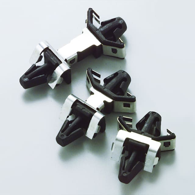
As a solution, we developed our multi-functional FG series that combined mechanical features and EMC grounding elements.
Noise Suppression by Multi-point Ground
|
Series ground
|
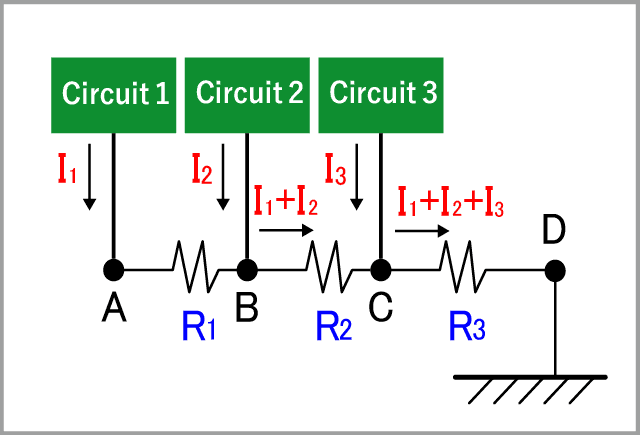
In series grounding shown in the right figure, common mode currents I1, I2, and I3 generated in circuits 1, 2, and 3 pass through a common ground and are connected to FG. In this state, common mode voltage is generated by the current and resistance (common impedance) at each point; and the ground potentials A, B, C, and D of each circuit are unstable and affect each other |
|
Single-point ground
|
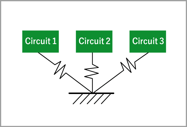
By using a single-point ground, common impedance is eliminated, and the ground potential of each circuit is determined only by the common mode current and ground impedance of each circuit. |
|
Multi-point ground |
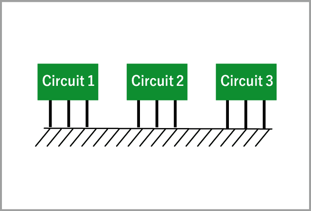
With higher frequencies in circuit designs, wire inductance increases. This leads to higher impedance which is undesirable for noise performance. Even with a single-point ground, the ground impedance increases at high frequencies and the ground potential becomes high. |
- Overview of EMC Grounding (GND)
- EMC Grounding Techniques
- Components for EMC Grounding


